I am currently working on STM32F103RB as a beginner. For that, I am undergoing training from a tutorial where the matter requires this :
Let’s suppose that we want to configure pin 5 of port A as input floating. We must then assign the binary value 0b0100 to bits b23 b22 b21 b20 of the CRL register
Here is the code from the tutorial:
GPIOA->CRL = GPIOA->CRL & ~(0xF << 20);    // Set bits b23 b22 to 0 b21 b20
GPIOA->CRL = GPIOA->CRL | (0x1 << 22);     // Set b22 to 1
The way shown above taken in the tutorial seems to me strange because I do not see the link with the pin 5 and the b20, b21 b22 and b23. Also About what I have understood, the CRL register is not supposed to contain b20, b21 b22 and b23.
Can someone explain to me how he has understood these two lines?
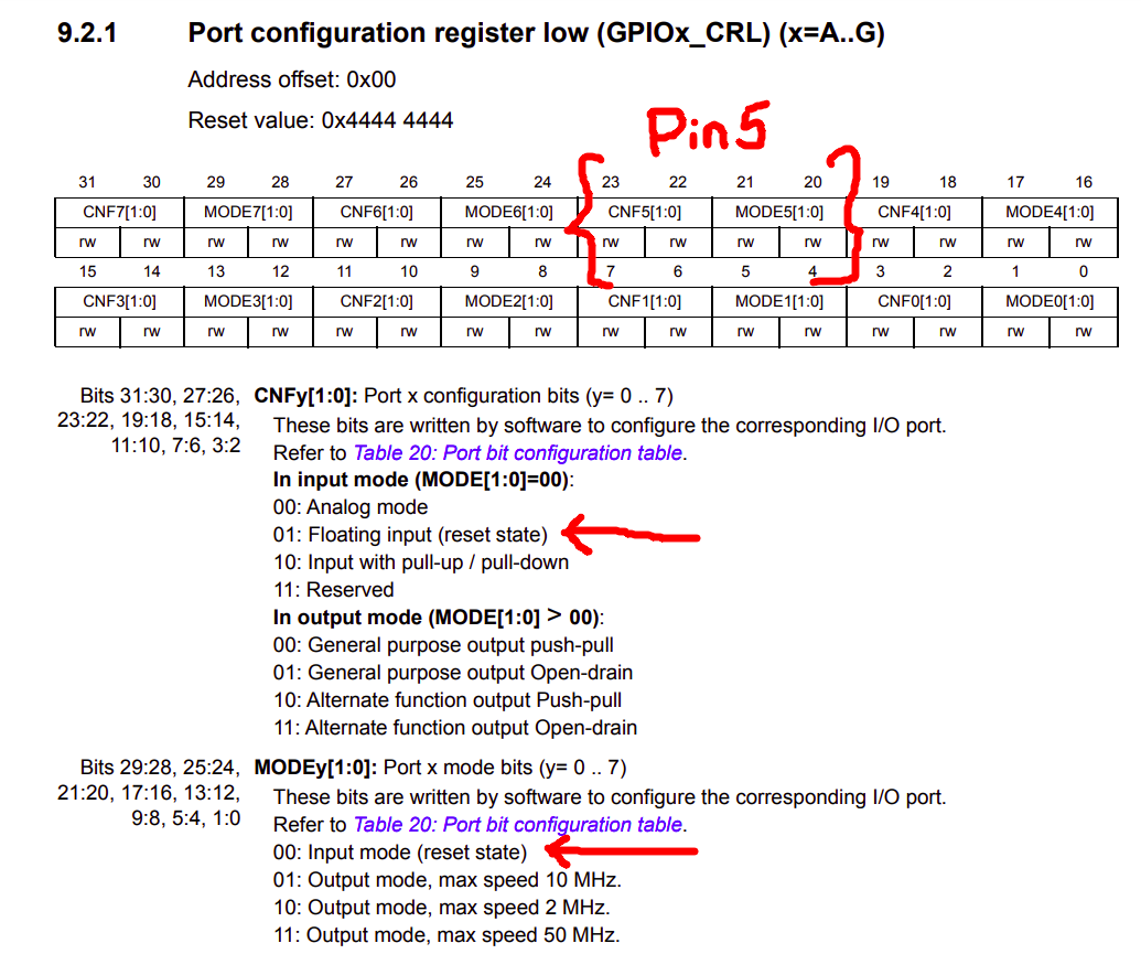
There is a link. The GPIOx_CRL is the configuration register to control the modes of pins on ports (A to G). The GPIOx_CRL register is a 32-bit register, of which the first 4 bits are used to configure the mode (See the arrow in the below image) of PIN 0. Similarly, bits 20,21,22, and 23 are for configuring modes of PIN 5.
Exactly,
01 to bits 23 & bits 22 ------> Floating input
00 to bits 21 & bits 20 ------> Input mode
See the image below, I hope you get an idea. As I can see that there is nothing wrong with your tutorial.
Now, I figure out better through your explanation from the drawings. So as far as the exercise is concerned why it is important to have these two lines? I mean why Set bits b23 b22 b21 b20 to 0 and why to Set b22 to 1 in order to configure the pin 5 as input. In my opinion, we could just assign the binary value 0b0100 to bits b23 b22 b21 b20 of the CRL register and How bits b23 b22 b21 b20 are all contain in 20 like mentioned in the first comment?
I have just understood that the second line of the code is the mask set in order to make the pin either in Input or in output. But what I still don’t understand is the first line :
GPIOA->CRL = GPIOA->CRL & ~(0xF << 20); // Set bits b23 b22 b21 b20 to 0.
Especially when the comment says that (0xF << 20) here 20 represents the bits b23 b22 b21 b20 to 0
Can I have an explanation about it Please?
Best regards,
If you take a look at the GPIOx_CRL section in the technical reference manual of your STM microcontroller, you could find the Reset Value of the GPIOx_CRL register which is 0x44444444 (It’s in the image above). Every time when you reset the microcontroller, the value in the GPIOx_CRL register resets to 0x44444444.
GPIOA->CRL = GPIOA->CRL & ~(0xF << 20); will rewrite every bits in the GPIOx_CRL register to zero.