555 timer working … Anyone give a explain
See this video. Hope it helps.

1 Like
The 555 timer is a digital-to-analog integrated circuit whose internal structure consists of three series-connected 5k resistors, two comparators, an RS flip-flop, an inverter, and a discharge switch tube T. The three series-connected resistors are connected to the power supply VCC, and the voltage drop across each resistor is 1/3 VCC. The three series resistors are connected to the power supply VCC, the voltage drop across each resistor is 1/3 VCC. 2/3 VCC has connected to the in-phase side of the comparator above, and 1/3 VCC is connected to the inverter side of the comparator below. these two voltages should be remembered, and are often used.
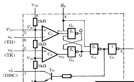
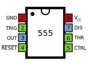
The RS trigger is a bistable trigger with 0 state and 1 state. 3 pin is the output, 7 pin is the discharge side, if the output is low potential, the RS trigger Q terminal is set to 1, the switch tube is discharged, 7 pin is pulled down to low potential; if 7 pin is connected to the pull-up resistor, the potential of 7 pin is the same as the output 3 pin. The same.
When the input signal is input and exceeds, the flip-flop is reset, the output of 555 outputs low at pin 3, while discharging, and the switch tube is on; when the input signal is input from pin 2 and below, the flip-flop is set, 555 outputs high at pin 3, while discharging, and the switch tube is cut off. It is the reset terminal, when it is 0, the 555 output low level. Usually, the terminal is open or connected to VCC.
1 Like