PIC Microcontroller
According to Wikipedia, PIC is a family of microcontrollers made by Microchip Technology, derived from the PIC1650 originally developed by General Instrument’s Microelectronics Division. The name PIC initially referred to Peripheral Interface Controller, then it was corrected as *Programmable Intelligent Computer. The first parts of the family were available in 1976; by 2013 the company had shipped more than twelve billion individual parts, used in a wide variety of embedded systems.
Internals
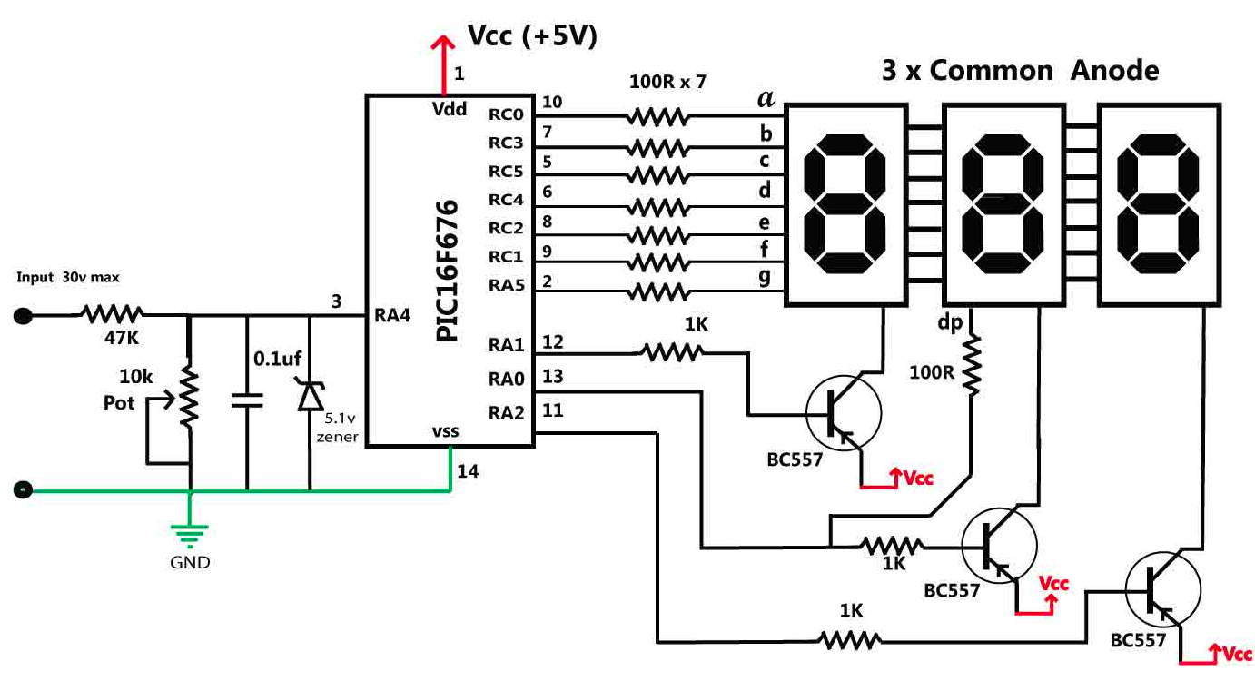
The PIC microcontrollers are very popular due to its cheap price, simple package, and its uncounted applications. One of the major advantages of PIC16F676 is its internal 10-bit ADC ( analog to digital converter). An analog to digital converter converts an analog signal into a digital form. In this project, we will use PIC16F676 microcontroller to design a 30V DC voltmeter. After successful completion of this project, you would be able to use this device in various systems to measure its output or input voltage. Follow the schematics as given below. You can easily adjust the accuracy of the voltmeter by changing values of the 47K resistor and 10k trim pot. Once complete, please don’t try to use this voltmeter to measure voltages on circuits having voltages above 30V as this can damage the PIC16f676 microcontroller.
Circuit Diagram
Please follow the circuits as given below:
Source Code
Compile and upload the source code given below to your microcontroller once the circuit is fully set up.
#include <htc.h>
__CONFIG (FOSC_INTRCIO & MCLRE_OFF & BOREN_ON & CP_OFF & CPD_OFF & WDTE_OFF & PWRTE_ON );


#define SPORT PORTA
#define DPORT PORTC
const char SegCode[11] = {0x40,0x57,0x22,0x06,0x15,0x0C,0x08,0x56,0x00,0x04,0xFF};
	//                       0    1    2    3    4    5    6    7    8    9
const char Column[3]   = {0x02,0x01,0x04};
static char Segment[3] = {0x7f,0x7f,0x7f};
static unsigned char ColCount=0x00;
void CPU_SETUP(void);
void Display(void);
void HTO7S(unsigned int Num);
void delayMs(int x);

unsigned int result;
unsigned int readAdc(void);
void interrupt  timer1_isr(void)
{
if(PIR1bits.TMR1IF==1)
{
PIR1bits.TMR1IF = 0;
	TMR1H=0xDF;
Display();
}
}
void main()
{
	unsigned char i;

	CPU_SETUP();
	while(1)
	{
		result=0;
		for (i=0;i<3;i++)
		{

			delayMs(1);
			result=result+readAdc();
		}
				HTO7S(result/3);

		delayMs(200);
	}

}

void CPU_SETUP()
{
	CMCON =0x07;		//Turn off comparator module
	ANSEL =0x8;			//AN3 as analog input
	ADCON1 =0x60; 		//clock/64
	ADCON0 = 0x8D;
   	TRISA=0b00011000;
   	PORTA=0x27;
   	TRISC=0b00000000;
   	PORTC=0x37;

   T1CON= 0x00;
  	TMR1H=0xDF;
   	INTCONbits.GIE =1;
	INTCONbits.PEIE=1;
	PIE1bits.TMR1IE =1;
 	T1CONbits.TMR1ON=1;
}
unsigned int readAdc()
{
unsigned int res;
ADCON0bits.GO_DONE =1;
while(ADCON0bits.GO_DONE ==1);
res=ADRESL+(ADRESH*0x100);
return(res);
}
//-------------------------------------
// Display routine
//-------------------------------------
void Display()
{
	PORTA = 0b00100111;	  // off all digits column and Segment G
	PORTC = 0b00111111;   // off segment a-f


	if (ColCount>=3)
	ColCount=0;

	DPORT = Segment[ColCount];
	SPORT = ((Segment[ColCount] & 0b01000000)>>1) | (Column[ColCount]^0x07);
	ColCount++;
}

//--------------------------------------
// Convet HEX 2 byte to 7-Segment code
//--------------------------------------
void HTO7S(unsigned int Num)
{

	unsigned int res;

	res = ((30*Num)%1023)/100;
	if(res==10)
	{
	Num=Num+1;
	res=0;
	}
	Segment[2]=SegCode[res];

	res = (30*Num)/1023;
	Segment[1]=SegCode[res%10];

	Segment[0]=SegCode[res/10];
	if (Segment[0]==0x40)
	Segment[0]=0xFF;

}

void delayMs(int x)
{
int i;
for (x ;x>0;x--)
{
for (i=0;i<=110;i++);
}
}