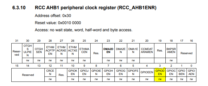
Ok i did not check the data sheet yet, I only used the data sheet snippets from the reply message before.
But after a short look I think your code is ok. The only thing you did wrong is you used the GPIOA pointer instead of GPIOD. I think you do not have to change the RCC->AHB1ENR |= (1U << 3); to RCC->AHB1ENR |= (1U << 4); because that would be wrong. You would enable the clock on GPIO E instead of GPIO D.
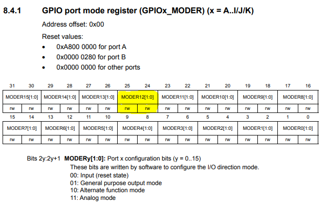
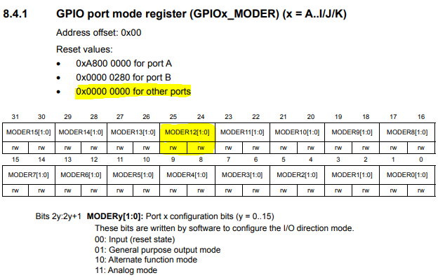
I think you should also keep the code to enable the alternate function but use the GPIOD pointer. Because GPIOD->MODE |= ~(1UL << (12 * 2)) does the wrong thing. It does not set a zero to the 24th bit as expected. It does an OR operation with the whole register and 0xFEFFFFFF. So please do not change your code there. Just adjust the GPIOA pointer to the GPIOD.
And just after a short look I am not sure why you have those two for loops in you main function inside the while loop. Because the thing is, if you have enabled auto reload on your timer (check if it is enabled) you should not load constantly values into the capture compare register.
Your timer counts from zero to the value stored in the ARR register and if it reaches the value in the CCR the PWM signal changes its polarity. Means the ARR register defines the frequency of your signal and the CCR defines the duty cycle.
I also found a nice video on youtube that really should help you on this problem. So just check it out and tell me if you have further questions: Stm32 Timers in PWM mode - YouTube
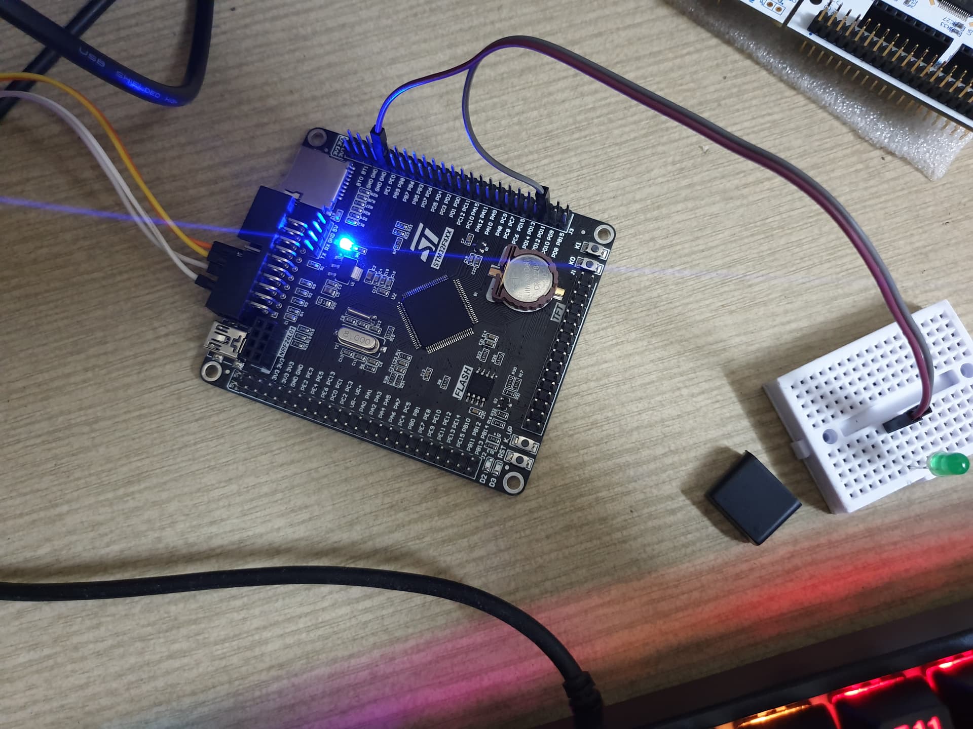
Thank you for the response and thank you also for those data sheet screen shots. They are really helpfull to analyze this problem here
Yes you are right that, because the default value of the register is zero, your code will work also. But the thing is, that it only works if bit 24 is zero. Otherwise you would do an OR operation on bit 24 with zero. The result would be one. This would not be the outcome that was expected.
And with your code, you will also set all the other bits in the register. What would be bad if those bits matter.
I totally agree with you that for this program here, your approach would work because we have a register that holds its defult value and all the other bits in the register do not matter.
Do not understand me wrong, but this is not a good way to do it, because if you extend the program with new features, this can easaly lead to bugs if you do not pay attention.
So I would always use registerName &= ~(1U << bitNumber) to clear bits and registerName |= (1U << bitNumber) to set bits. This is how it should be done in my mind
But I am here for further discusion if you see it in another way