In this tutorial, we are going to control the intensity of a 100W AC Bulb without using Zero Crossing Detector so you can also other Libraries which uses Interrupts such as SoftwareSerial.h.
Despite the simplicity of the Zero Crossing Detector circuit the software needed was a bit complicated as it needed to keep looking always of the zero crossings of the AC signal, then keep a watch on the time and then finally open the TRIAC. So to avoid letting the Arduino just wait for most of the time, an interrupt and a timer was necessary.
We will just use PWM, like with leds. Someone looking for that would no doubt end up at design by Ton Giesberts/Elektor Magazine that can do PWM of an AC source.
The components Required for this Tutorial are listed below :


BRIDGE RECTIFIER BR1010

OPTOCOUPLER 4N35

IRF730 POWER MOSFET
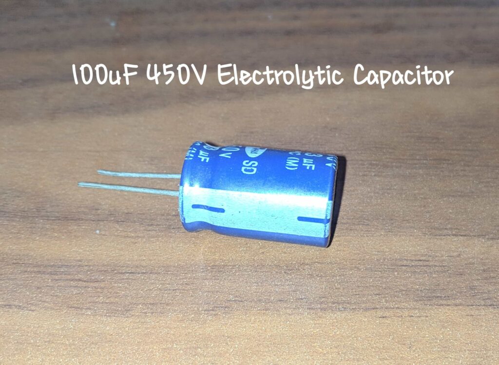
10 0uF 450V Electrolytic Capacitor
CAPACITORS
100K 0.5W Resistor & 6.8K 0.5W Resistor

RESISTORS
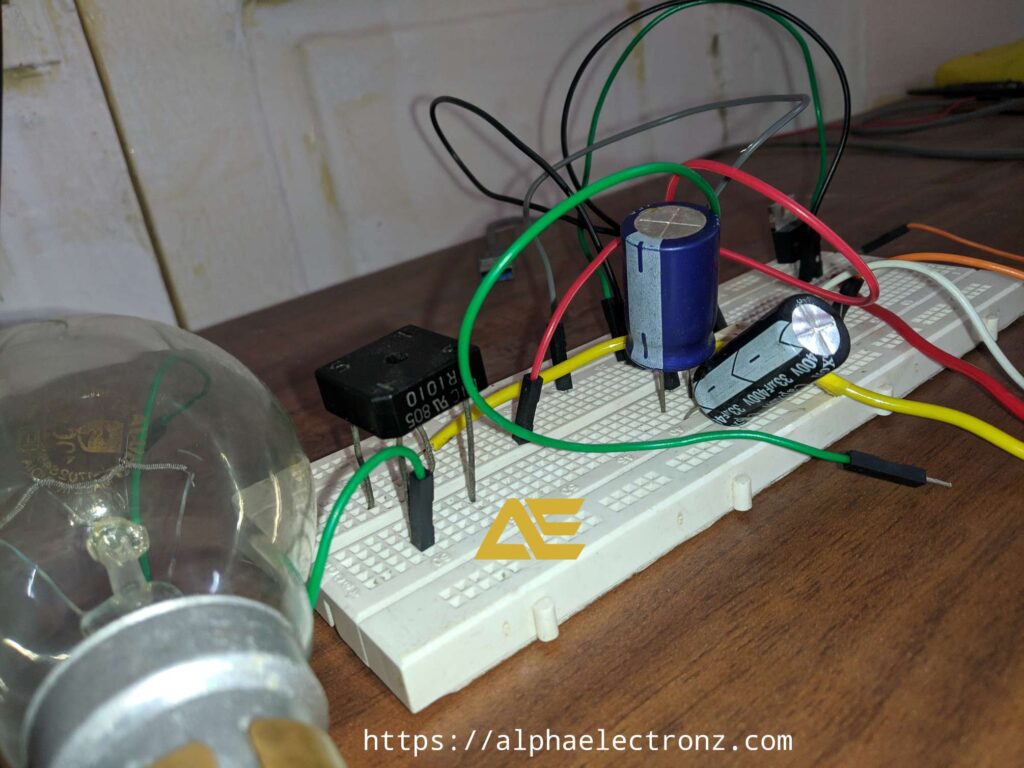
Circuit Diagram
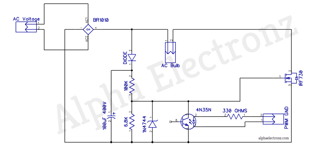
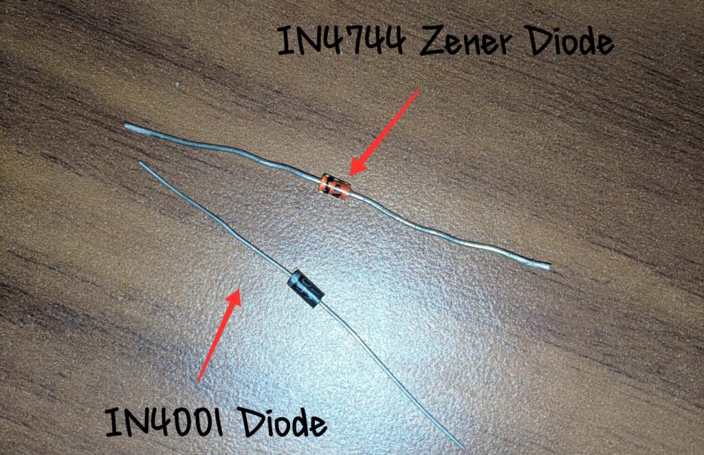
As you can see in the above circuit diagram the AC Input is rectified using a BR1010 Bridge Rectifier (Datasheet at the end of the post) and that is provided to the voltage divider of resistors 100K and 6.8K of 0.5 or 1W to provide switching voltage to the Power MOSFET IRF730 which has max gate to source voltage of +/- 20V.
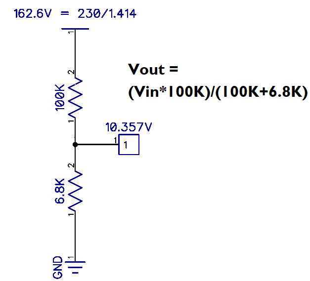
Voltage Divider Formula for Gate Switching
Thus we are applying 10.357V on the gate of MOSFET IRF730 for switching.
Code For dimming Effect
int ledPin = 9;    // LED connected to digital pin 9

void setup() {
  // nothing happens in setup
}

void loop() {
  // fade in from min to max in increments of 5 points:
  for (int fadeValue = 0 ; fadeValue <= 255; fadeValue += 5) {
    // sets the value (range from 0 to 255):
    analogWrite(ledPin, fadeValue);
    // wait for 30 milliseconds to see the dimming effect
    delay(100);
  }

  // fade out from max to min in increments of 5 points:
  for (int fadeValue = 255 ; fadeValue >= 0; fadeValue -= 5) {
    // sets the value (range from 0 to 255):
    analogWrite(ledPin, fadeValue);
    // wait for 30 milliseconds to see the dimming effect
    delay(100);
  }
}
Now Connect the AC Wires Carefully and Upload the code to Arduino Uno and watch your 100W AC Bulb Fade.
