Coupling capacitors used in modern bipolar amplification alter the waveform of non-sinusoidal signals. Due to their RC time-constamt which limits their maximum charging rate. Therefore omitting them from amplifier designs may have desirable qualities, in audio signal amplification. Stabilization of bipolar transistors is a necessity for linear amplification, and that can be accomplished with resistors placed in series with the emitter, base, and collector terminals. This creates a fluctuating DC output at the collector of a common emitter biased amplifier. To convert to an AC output, it is necessary to use a dual transistor circuit arrangement similar to the old style FET or Tube amplifier designs. In those designs the two input leads of an acoustical signal, drove the gate or grid of two FETs or Tubes, or in this case, would drive the base of the two bipolar transistors. This creates a push-pull action for AC output from the amplifier.
Do you have an image from what you have written?
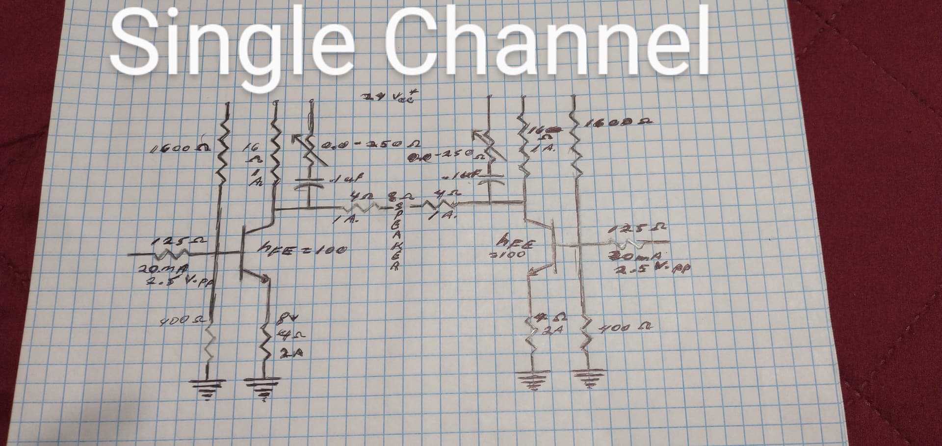
Note the shunt capacitor across the collector resistor. It isn’t in series with any of the signal amplification, so hopefully little RC signal alteration. And it’s intended function is for restoring any “capacitive signal alteration” during prior amplification. (Restoration of the frequency and volume fading of musical notes) This sketch is of a Class A, AF, Power amplifier.
Nysee, please delete all sketches of partly complete amplifiers. The most recent “complete sketch” should be enough for conveying my point about capacitors altering the waveform of an acoustical signal. But include all of the related text.
(Only one sketch need be linked to my post, and it’s proposed circuit).
1 Like